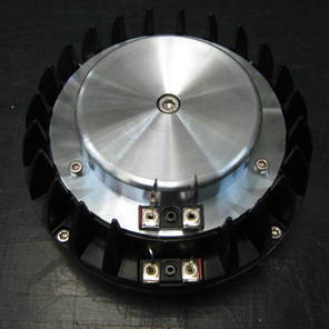
DCX464 HF Diaphragm Replacement
DCX464 HF Diaphragm Replacement
DCX464 HF Diaphragm Replacement
Here is the procedure to follow to replace the DCX464 MF driver diaphragm
Caution: While we are pleased to provide this information on how to replace a diaphragm, we strongly recommend that you seek professional support for these procedures in order to ensure long term component performance.
If you wish to proceed, please follow these steps very carefully, and read the entire document before starting the process.
Supplies and Tools Required:
- Soldering gun
- Screwdriver for 4 and 6 mm Hex screws
- Tweezers
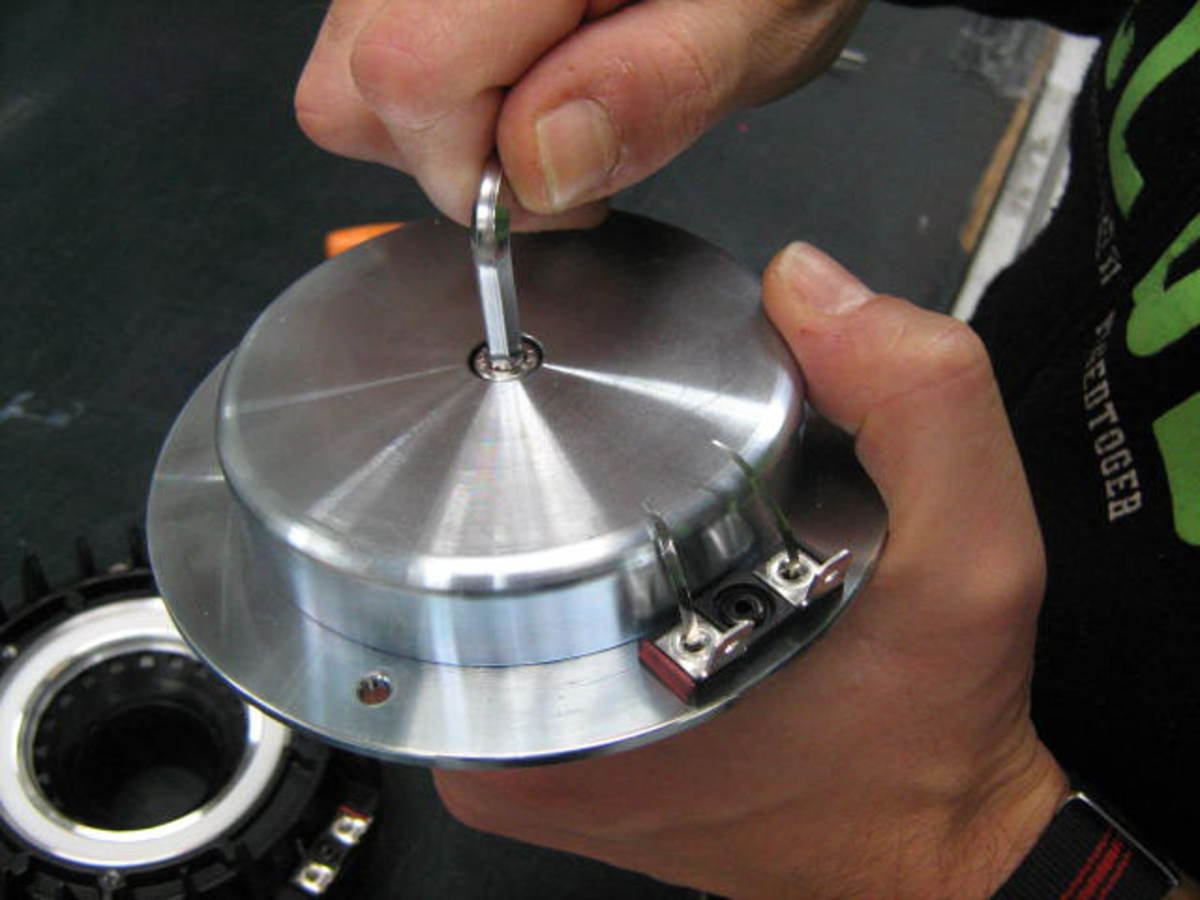
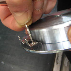
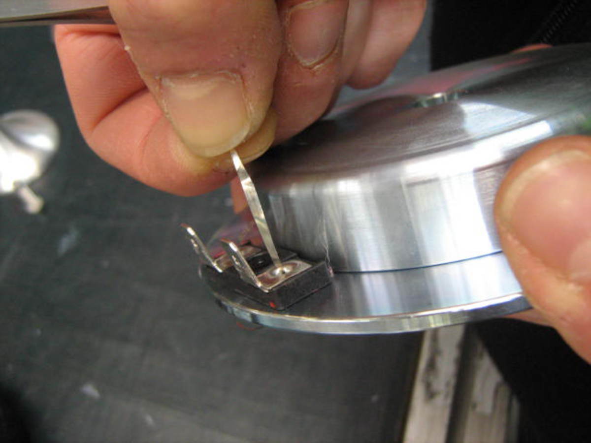
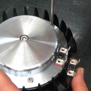
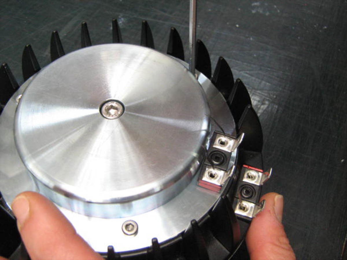
1. Unsolder the lead wires from the fast-on terminals, being careful not to overheat the Faston connector.
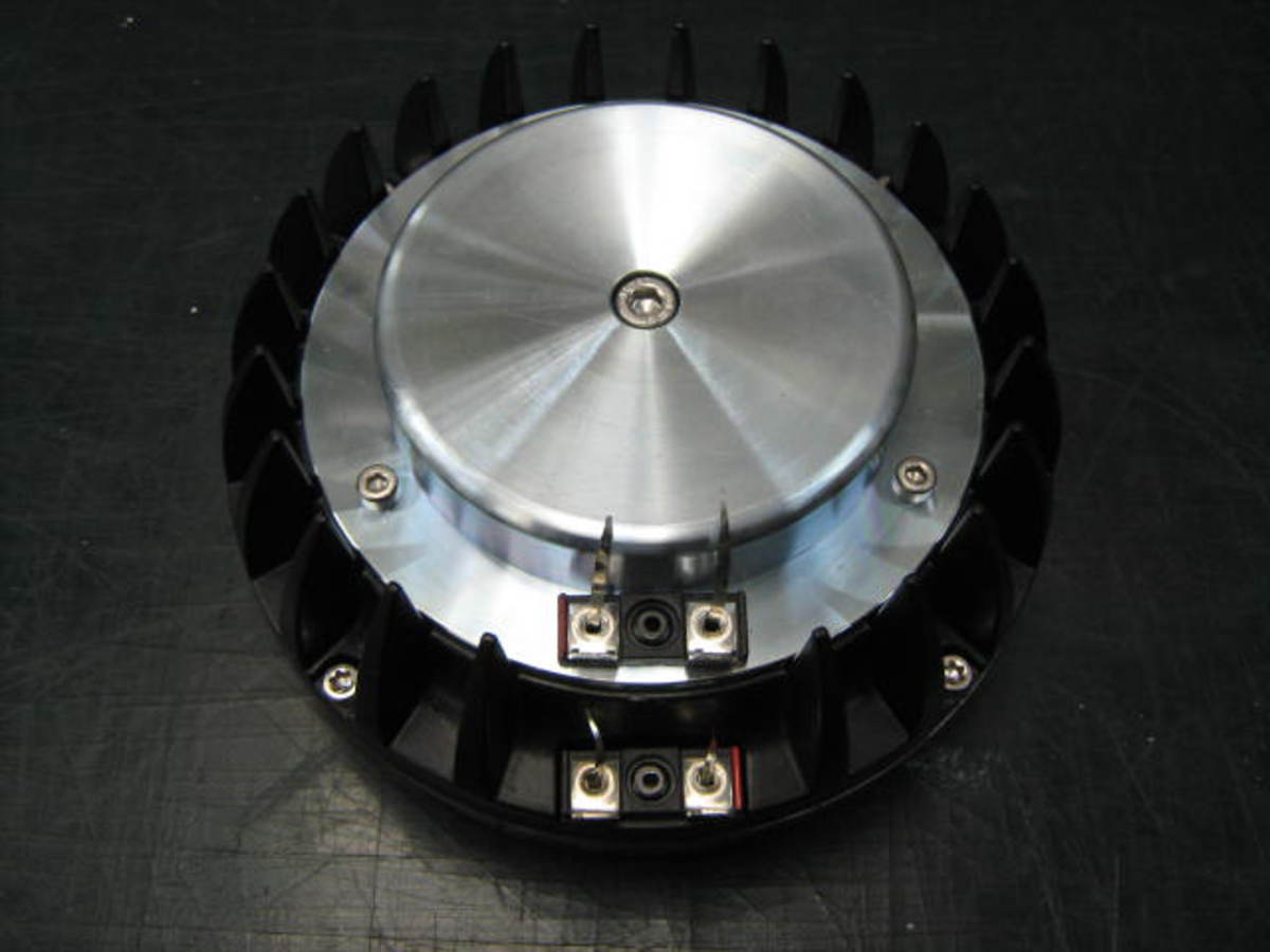
2. Remove the three outer screws
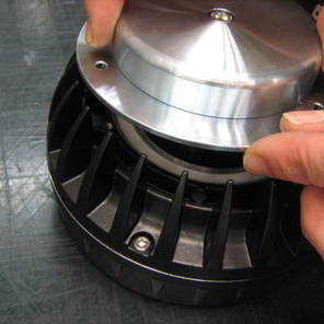
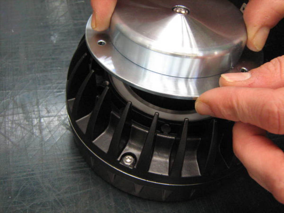
3. Pull up the central part of the transducer, taking it out from the magnet structure
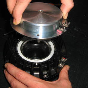
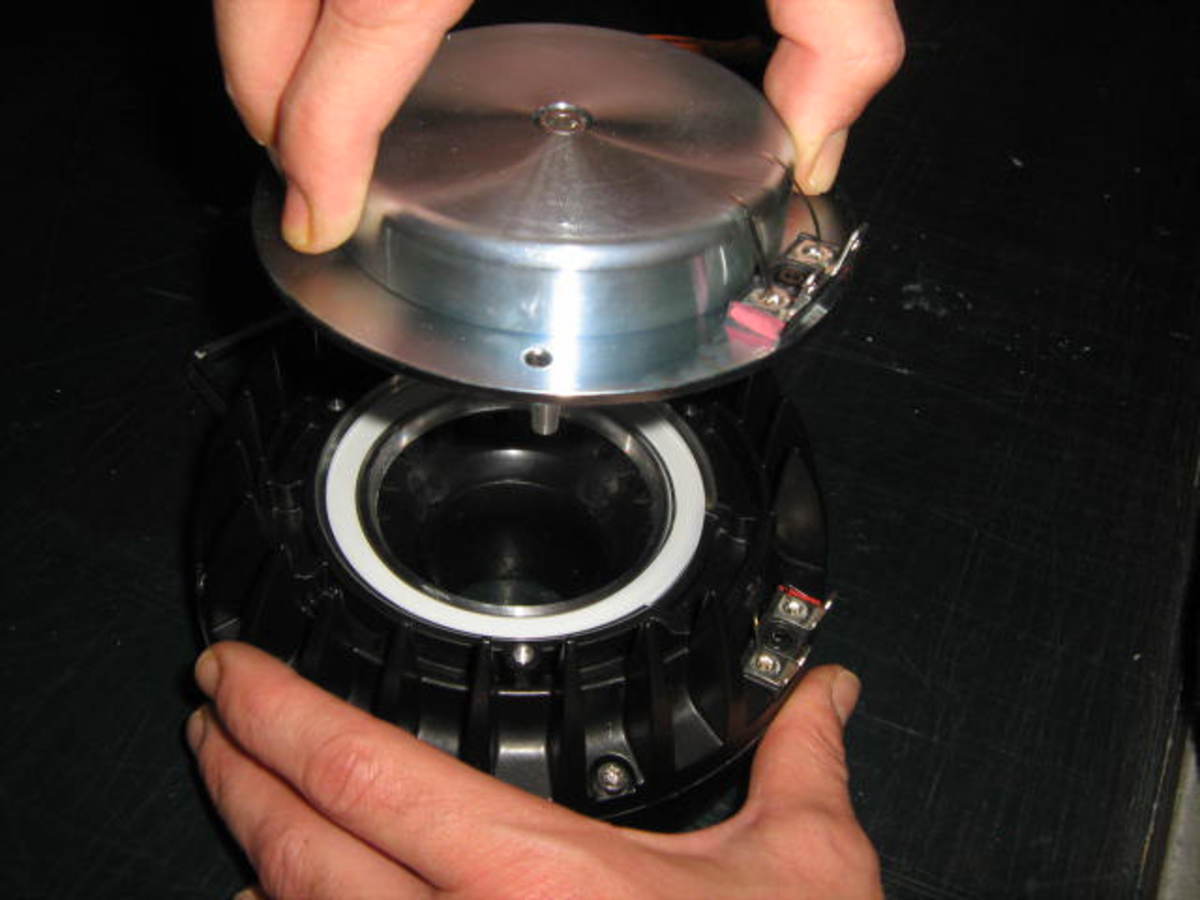
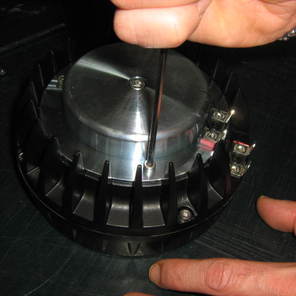
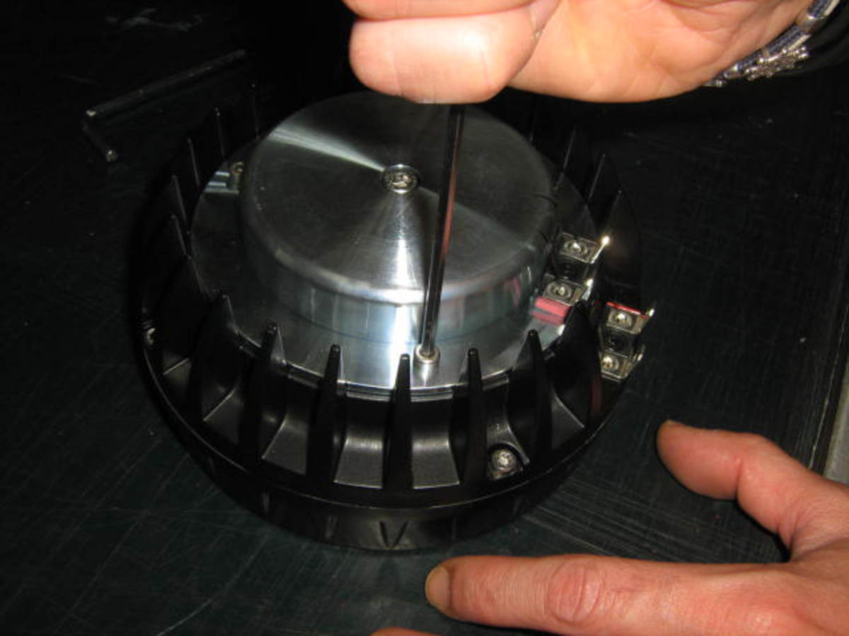
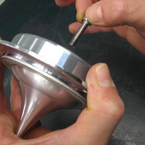
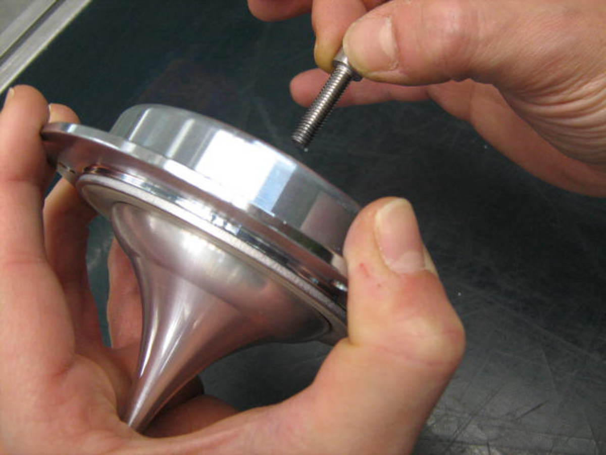
4. Remove the HF phase plug removing the central 6 mm Hex screw
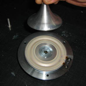
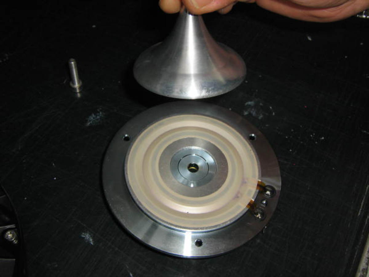
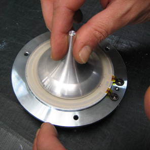
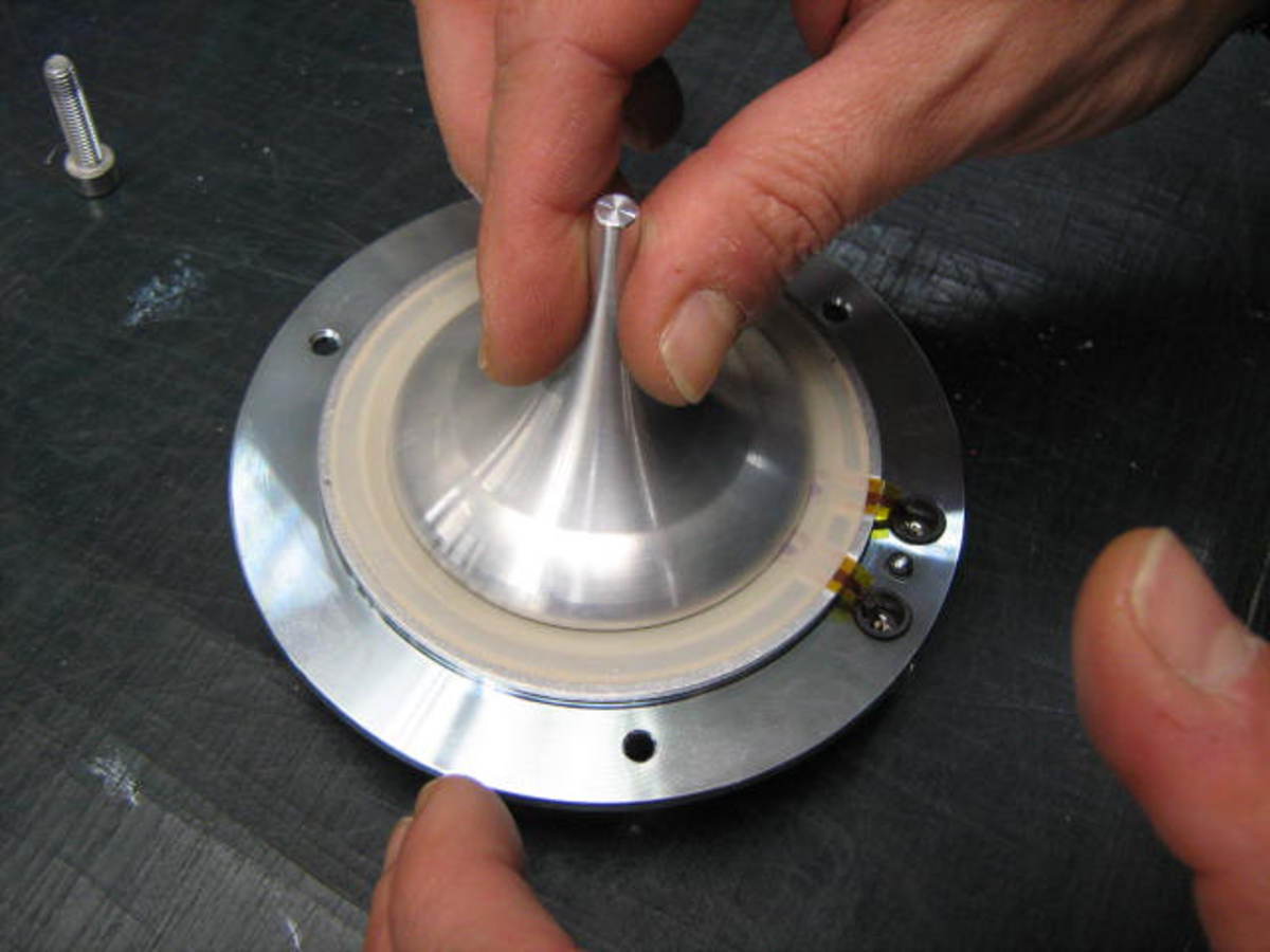
5. Take out the diaphragm carefully, holding it from the outer edge
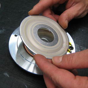
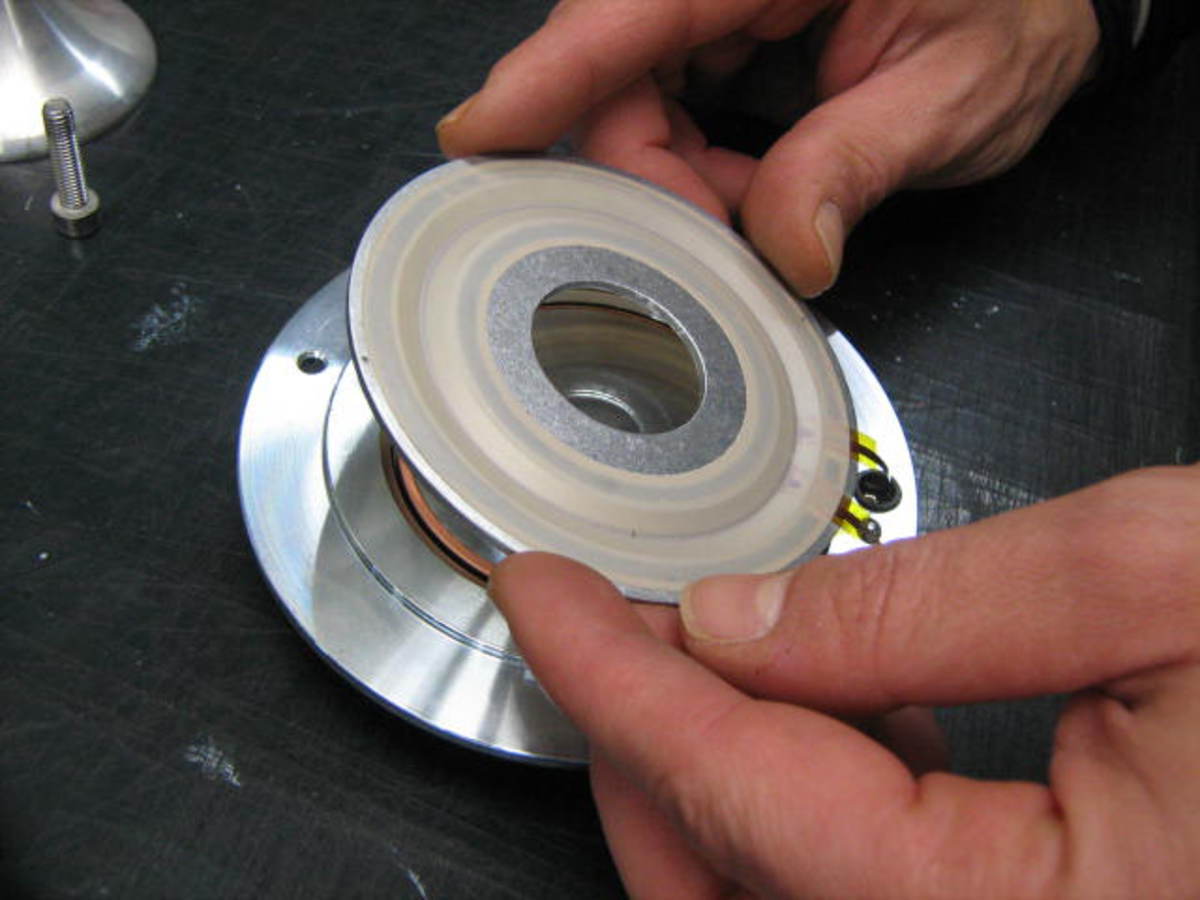
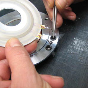
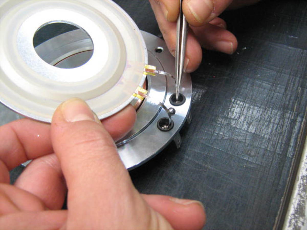
6. Put the new diaphragm in place. Use the tweezers to insert the lead wires into the fast-on terminals
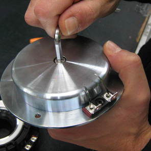
7. Re-assemble the HF phase plug on the magnet structure, fixing it with the central 6 mm screw.
8. Re-assemble the HF unit on to the MF unit.
9. Fix the screws in place.
The recommended screw torque is about 3 Nm.
10. Solder the lead wires on the Fast-on terminals, being careful not to overheat the Faston connector.
11. It is advisable, at this point, to do an acoustic test, to verify that you have installed the diaphragm properly:
a. Hook up the driver to an oscillator and an amplifier.
b. Conduct a sweep test from 200 Hz to 1000 Hz, applying 3 – 4 V rms. During the test you should not hear any noise or strange vibration; instead, you should hear a "clean" sweep sound. If not, it is possible that some particles of foreign matter were left in the gap.